 The very first question I get was: what kind of hardware are you using ?
In fact, I searched a little bit on the web, and I came to the conclusion that the simplest solution was to use Maxim 1-wire bus. This bus is very simple (2 or 3 lines are needed, despite the name), and the devices I need (temperature probes) are simple and cheap !
There is a very interesting introduction video on Maxim’s web.
Products selection
I selected basic temperature probes (DS18B20) and I chose to cable them myself. Not only for the fun, or for the cheaper price, but also because it would allow me to better understand how all this stuff is working.
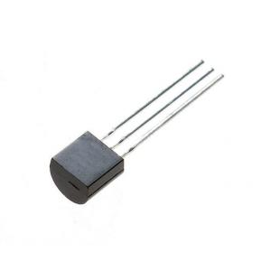
Those probes are very small (usual electronic transistor size).
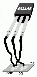
 Cabling is simple. I read several articles on the web saying that, for temperature probes, the best choice is to use “parasitic mode” (only 2 wires: Data and Ground). This implies to connect the +Vcc leg of each probe to the Ground, as shown on the picture here.
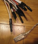
On the “other side” of the wire, we need a “converter”. I selected a very simple dongle: USB 1-Wire DS9490R (USB/RJ11). This dongle is very interesting for me: cheap (<30€), simple to connect to the computer (USB) and to the 1-wire (RJ11).
I decided to use my internal server (GEO, a physical server running Ubuntu Server distribution), always up and running to connect this USB dongle.
Last item: cable !
I search in my supplies, and selected a phone cable, with RJ11 male plug on it, to simplify connection with the dongle.
How much does it cost ?
Well, not a lot, as you can see on this bill. I ordered that on Internet, and get it delivered 2 days after… perfect !
Some manual work
It’s time to connect all those devices together.
I took my soldering iron, and start soldering…
Here again, browsing the web, I noticed an important advice: if you want a long distance 1-wire, it is recommended to use a “bus topology”, instead of a “hub topology”. This means the cabling has to go to the first probe, and the 2 wires then should continue to the next probe, and so on, until the last one…
Where are my 2 wires (out of the 6 available from my RJ11 plug) ?
Well… that’s all what is needed !
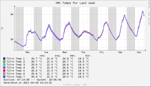
I ran some tests during one week, putting all my 7 temperature probes together, to check accuracy: it looks very good:
Next article: the software part…


Cool this first article.
Do you know if there is some way to use wifi between “probes network” and server ?
The idea will be to have probes outside, that could communicate to the PC inside via wifi.
Not using 1-wired solution. This solution is designed to go… on a wire !
But there are different possibilities, like X10 or Z-wire, that are using radio waves (as well as technics based on the promising Zigbee chip).
Next parts, next parts !!!
Pingback: Temperature probes (part 2)